
Identifying metal keypad pins requires a multimeter set to continuity mode. Engineers test each pin against known row/col combinations, looking for a beep or zero resistance. Keypado’s لوحات مفاتيح معدنية مصنوعة حسب الطلب, trusted by over 200 clients, simplify this process with clear documentation and fast sampling support.
احصل على عرض أسعار مخصص للوحة المفاتيح المعدنية من Keypado
What tools do you need to identify keypad pins?
A digital multimeter in continuity mode is the primary tool for tracing which pins connect to which rows and columns. Bench technicians rely on this method because it gives immediate, audible confirmation of a connection. A standard 4×4 matrix layout requires eight digital pins to cover every row and column connection. The multimeter approach scales cleanly across common configurations.
What does a multimeter continuity test actually reveal?
The continuity test answers one question: does this pin connect to that row or column? Place one probe on a pin, press a key, and touch the other probe to the remaining pins. A beep confirms the connection. Repeat this for each key to map the full matrix.
Set the multimeter to continuity mode.
Place one probe on the first pin.
Press a single key and hold it down.
Touch the second probe to each remaining pin until the meter beeps.
Record which pin pairs with which key.
Repeat for every key on the keypad.
What if the continuity test fails on a metal keypad?
Some metal keypads include diodes or non-standard internal wiring that defeats a simple continuity check. A forum thread on Arduino.cc from January 7, 2018 describes exactly this frustration: a 4×4 keypad with 16 buttons and two apparent diodes resisted standard multimeter tracing. When this happens, the fastest path is factory documentation. Keypado engineers custom matrix, USB, and industrial keypad interfaces, sizing the pin count to each OEM’s actual layout. The company provides factory-direct engineering support from Yuyao, Zhejiang, China. OEM designers receive pinout diagrams matched to the exact build rather than a generic reference sheet.
How does a matrix keypad pinout actually work?
A matrix keypad pinout organizes switches into a grid of rows and columns. Each key press bridges one row and one column, creating a unique electrical path the controller reads as a specific input.
The physical wiring follows a simple rule. All switches in the same row share a common connection. All switches in the same column share another common connection. This arrangement slashes the number of I/O pins required. A 4×4 grid needs only eight pins instead of sixteen. A 4×3 layout uses seven pins. The savings grow dramatically as key counts increase.
Why do rows and columns share connections?
Sharing connections reduces wiring complexity without sacrificing functionality. Each intersection in the grid holds a push button switch. When a technician presses a switch, that single action connects its row to its column. The controller scans rows sequentially while monitoring column states. A detected connection on a specific row-column pair identifies the pressed key instantly.
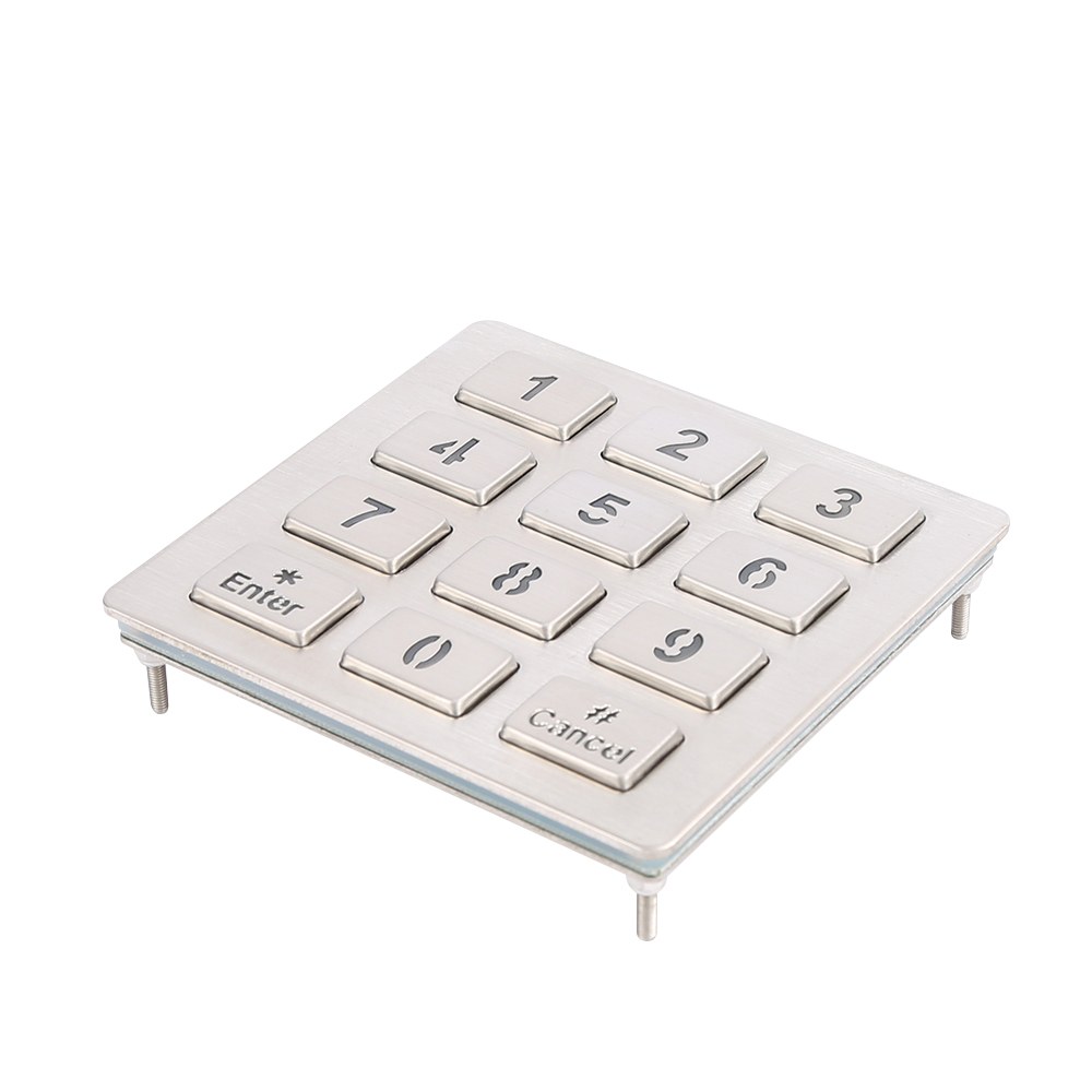
Keypado builds custom metal keypads with 3×4 or 4×4 layouts that fit specific panel designs. These rugged configurations use the same matrix principle while adding vandal-resistant metal construction. Engineers working with industrial equipment often need to identify keypad pins before integration. A multimeter set to continuity mode reveals the row and column groupings quickly. Probing pin pairs while pressing each button maps the entire matrix.
How do you test metal keypad pins on an unfamiliar unit?
Testing begins with a continuity check between every pin combination. Press one button at a time and note which two pins show a closed circuit. Those two pins represent the row and column for that key. Repeating the process for all buttons builds a complete pinout table. Diodes on some keypads complicate the reading. A standard continuity test fails when diodes block current in one direction. Switching the multimeter to diode mode solves this problem. The meter then shows the forward voltage drop, confirming the connection path.
For OEM deployments, Keypado provides custom industrial pin keypads with documented matrix assignments. Factory documentation eliminates guesswork during assembly. Batch inspection reports verify every unit matches its specified pinout before shipping.
How do you trace rows and columns with a multimeter?
Tracing rows and columns on a keypad requires a multimeter set to continuity mode. The process maps which pins connect when a specific key is pressed, revealing the matrix layout underneath. Without this mapping, integrating the keypad into a controller becomes guesswork that wastes engineering hours and risks miswired prototypes.

احصل على عرض أسعار مخصص للوحة المفاتيح المعدنية من Keypado
What preparation is needed before testing?
A bench technician needs a digital multimeter with an audible continuity buzzer, the keypad’s pin header or wire leads, and a notepad. The keypad sits disconnected from any circuit. Pull-up resistors connected to the rows ensure they remain in a HIGH state when no key is pressed, as noted in a Jameco tutorial on matrix keypads. That detail matters later during integration but does not affect the continuity test itself.
Follow these steps to identify keypad pins and map the matrix:
Set the multimeter to continuity mode and verify it beeps when the probes touch.
Pick one pin as the reference and probe every other pin while pressing a single key.
Note which pin pair beeps only when that key is held down.
Release the key and confirm the beep stops, ruling out permanent connections.
Repeat for every key until all row and column pairs are documented.
Continuity testing between pins reveals which pairs are connected when a key is pressed. An Arduino forum discussion confirms this approach, though one user noted that diodes on the board complicated the readings. Diodes cause one-way conduction, so swapping probe polarity sometimes exposes hidden connections.
Why do some keypads confuse continuity readings?
Diodes embedded in the matrix block current in one direction. A standard continuity test shows an open circuit if the probes are oriented against the diode. Reversing the probes allows current to flow and solves the puzzle. Keypado’s metal keypads offer USB or matrix output for easy controller integration, eliminating the need for manual pin mapping on custom builds. The company’s rugged metal construction delivers vandal-proof, IP-rated durability, which suits OEM deployments where field technicians never touch a multimeter after installation.
How do you test metal keypad pins for switch integrity?
Testing metal keypad pins for switch integrity starts with a simple continuity check. A multimeter confirms whether each key press reliably connects its assigned row and column pin. When a switch is pressed, it connects a row to a column, as explained in the Jameco tutorial Teach and Learn: Working with Matrix Keypads. Without this connection, the controller never registers the input. Engineers lose hours chasing ghost faults that trace back to a single intermittent contact.
What tools are needed to test metal keypad pins?
A digital multimeter set to continuity mode is the essential tool. A pinout diagram for the specific matrix layout speeds up the process. For keypads with non-standard wiring, a logic analyzer helps map the scanning pattern. Bench technicians also keep a known-good microcontroller board handy to verify the full signal path under real scanning conditions.
How does a continuity test reveal a failing switch?
Set the multimeter to continuity or resistance mode.
Place one probe on the row pin and the other on the column pin for the switch under test.
Press and hold the target key firmly.
Observe the reading: a stable low-resistance value or an audible tone indicates a good switch.
Release the key and confirm the circuit opens completely.
An intermittent or high-resistance reading points to contact wear or contamination. Keypado’s vandal-proof metal keys are built to last millions of presses. A premature failure signals an environmental or integration issue rather than normal aging. The company’s ISO-certified quality control and batch testing catch these defects before units ship.
Beyond the switch itself, the housing matters. Keypado’s products are sealed to IP65+ against dust and water ingress. Moisture bridging row and column traces mimics a stuck key. A technician who skips the housing inspection chases a software ghost while the real culprit is condensation on the PCB. For a deeper look at how those ratings are verified, the process for testing metal keypad IP ratings follows strict IEC 60529 standards.
ماذا لو ظل ترتيب أطراف التوصيل غير مفهوم؟
A stubborn pinout often signals hidden components on the keypad’s circuit board. Some keypads include diodes for each switch, which complicates simple continuity testing and throws off standard multimeter readings. A technician probing a 4×4 matrix that refuses to resolve into clean rows and columns faces a real diagnostic puzzle.

احصل على عرض أسعار مخصص للوحة المفاتيح المعدنية من Keypado
Why do diodes confuse continuity tests?
Diodes allow current in only one direction. A continuity test sends a small voltage through the probes and expects a clear path. When a diode sits in series with each switch, the meter sees an open circuit in one direction and a voltage drop in the other. The result is inconsistent beeping and readings that seem to shift depending on probe orientation. This behavior masks the true row-column relationship and makes the matrix appear scrambled.
When should an engineer stop troubleshooting and seek factory support?
Persistent confusion wastes engineering hours and delays prototyping. Keypado offers free CAD review and customization support directly from the factory. The company’s engineers examine the actual board layout and resolve pinout ambiguities without guesswork. Keypado supports pilot runs with low minimum order quantities and quick sampling. A design team moves from a dead-end breadboard to a verified, production-ready sample in days rather than weeks. The company’s products are trusted by over 200 clients in more than 30 countries, a track record built on solving exactly these integration headaches.
الأسئلة الشائعة
What tools do you need to identify keypad pins?
A digital multimeter set to continuity mode is the primary tool needed to identify keypad pins.
What does a multimeter continuity test actually reveal?
A continuity test reveals whether a pin connects to a specific row or column. Press a key, probe each pin pair, and a beep confirms the connection, mapping the full matrix.
What if the continuity test fails on a metal keypad?
Keypado provides factory-direct engineering support from Yuyao, Zhejiang, China, with pinout diagrams matched to the exact build.
الخلاصة
So grab your multimeter, map those pins, and test every switch before you commit to a design. If the readings stay stubborn, the problem likely sits in the board’s hidden components, not your technique. That is the moment to stop guessing and let the factory’s engineers untangle the layout for you. A verified pinout turns a frustrating breadboard into a production-ready sample, and that clarity is worth the call.
 English
 Deutsch
 Français
 Polski
 Português do Brasil
 Español
 日本語
 Русский
 العربية
 Italiano
 Nederlands
 Türkçe
 한국어