
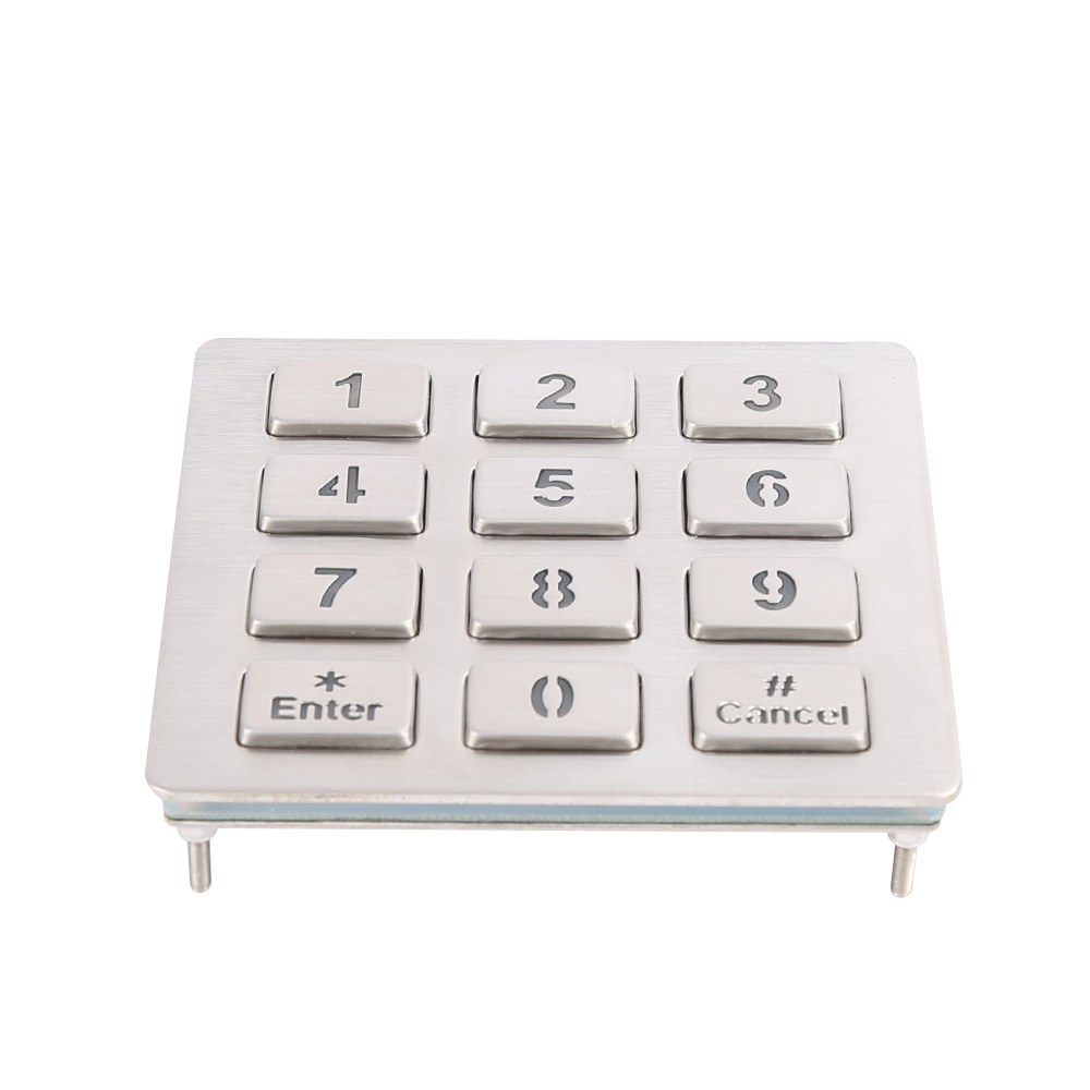
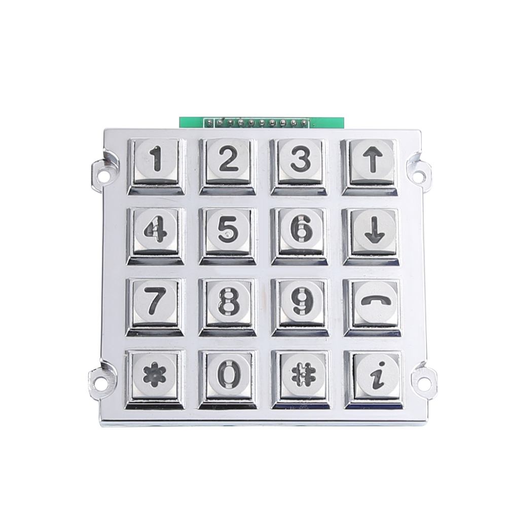
When it comes to check pins on a keypad with a multimeter, testing a matrix keypad‘s pins requires setting a multimeter to continuity or resistance mode, then probing pin pairs while pressing each button. A closed circuit produces a beep or near-zero ohms reading, confirming which pins belong to that key’s row and column. Rugged Keypado-style metal keypads use matrix wiring, so technicians should map all 16 buttons systematically before installation.
What Do You Need Before Testing Keypad Pins?
Three things matter most before probing any keypad: a multimeter set to continuity mode, a clear picture of the keypad’s layout, and knowledge of the output interface. Skipping any of these steps leads to wasted time and false readings on the bench. Industrial keypads aren’t wired like consumer remotes, so a little prep goes a long way toward accurate diagnostics.
Get a Custom Metal Keypad Quote From Keypado
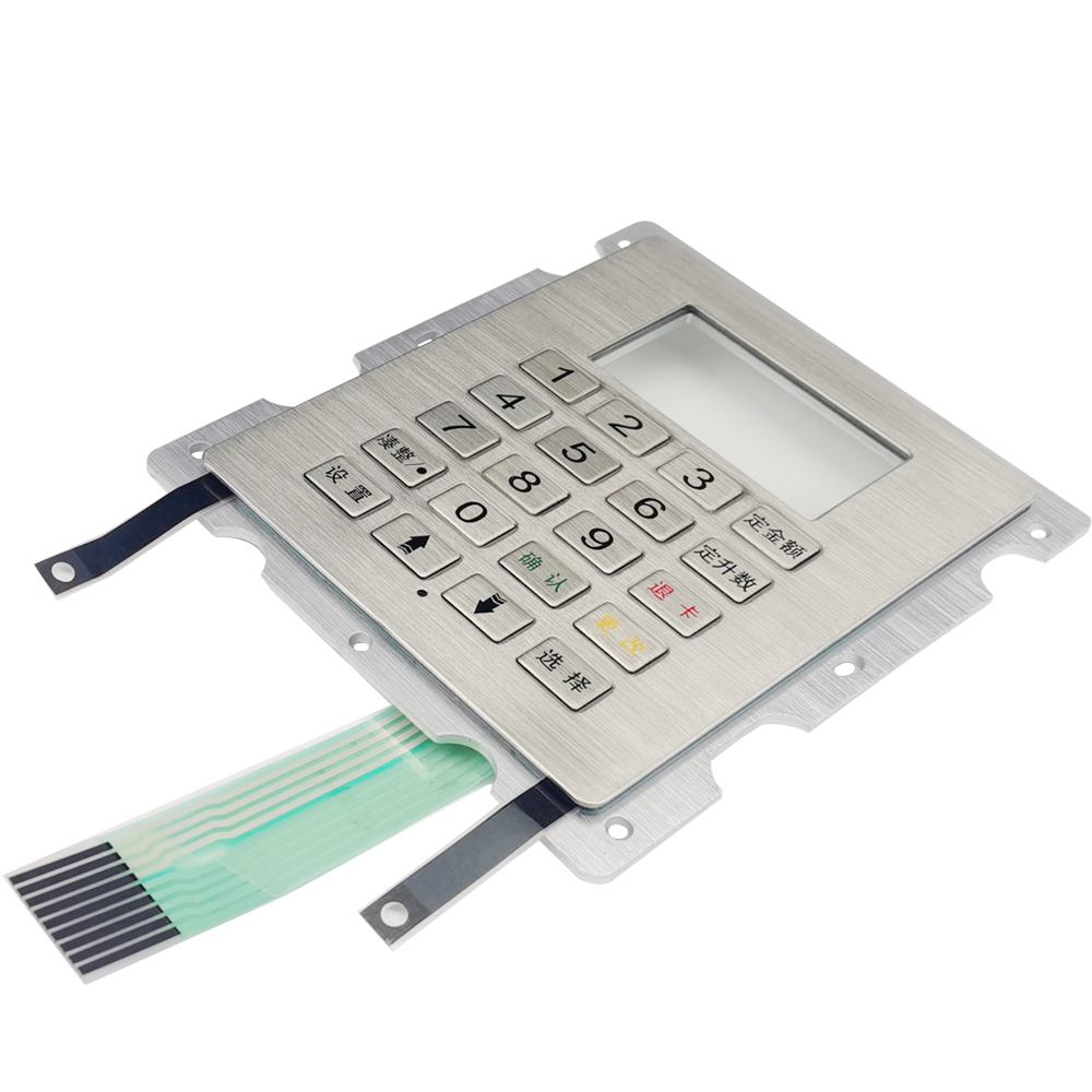
Metal industrial keypads typically expose their pins through a USB or matrix output. That connection point is exactly where a technician attaches a multimeter or controller during testing. Knowing which interface a given unit uses shapes the entire testing approach. A USB-output keypad behaves differently under a probe than a raw matrix connection does. Confirming the interface type first saves a lot of guesswork.
Does the keypad layout matter before testing?
Yes, layout matters quite a bit. Custom 3×4 and 4×4 layouts show up constantly on industrial panels, and each arrangement wires rows and columns differently. Assuming a standard layout without checking the actual configuration often leads to mismatched row and column readings, which throws off the whole test.
What multimeter setting works best for keypad pins?
Continuity mode is the standard starting point among engineers who need to check pins on a keypad with a multimeter. This setting traces exactly which pins correspond to which row or column on a matrix keypad, one connection at a time.
Before starting, gather the following:
A digital multimeter with a working continuity mode
A reference diagram or datasheet showing the keypad’s row/column layout
Clear visibility of the pin connector or output header
With these three items ready, a reliable pin test becomes far easier to run.
How Do You Identify Row and Column Pins?
Correct pin identification starts before any meter touches a connector. Matrix keypads group buttons into rows and columns, and each pin carries a specific signal. Mixing them up produces false readings and wasted troubleshooting time.
Why does pin order matter so much on a matrix keypad?
A row pin and a column pin look identical on the connector, but they behave differently in the circuit. Confusing the two is the single most common reason technicians get confusing continuity results. Knowing which pin is which, before applying probes, prevents that confusion entirely.
Engineers can follow a straightforward sequence to map the layout accurately:
Locate the connector or pin header and note the total pin count — a standard 4×4 layout typically breaks out to eight lines, four rows and four columns.
Set the multimeter to continuity mode and touch one probe to a single pin.
Press and hold one button while touching the second probe to each remaining pin in turn.
Record which pin produces a tone or reading — that pin pairs with the held button’s row or column.
Repeat across every button until the full row-and-column map is complete.
This process is exactly how technicians check pins on a keypad with a multimeter. It works whether the unit sits on a bench or stays mounted in an enclosure.
Keypado’s metal key switches hold up well through this kind of repeated poking and pressing. Rated for millions of presses, the same button gets tested over and over without the contact wearing down or the reading drifting between attempts. That durability matters during layout mapping, since a single pin often needs five or six presses before its role is confirmed.
One more diagnostic note worth keeping in mind: Keypado units carry IP65+ sealing against dust and water. So if a pin shows no continuity at all, moisture intrusion is an unlikely culprit. A loose connector or damaged wire almost always explains the open circuit instead.
How Do You Test Each Key With a Multimeter?
Testing a matrix keypad requires a specific lead setup before any button gets pressed. Skipping this order produces false readings and wastes diagnostic time on a working unit. A methodical, repeatable approach matters even more once a keypad design scales into production runs.
Get a Custom Metal Keypad Quote From Keypado
What’s the correct multimeter setup for a keypad?
Engineers should check pins on a keypad with a multimeter by inserting the black test lead into the COM port first. The red test lead then goes into the VΩ port. Only after both leads are seated should the probes touch the pins. This sequence prevents inaccurate voltage or continuity readings caused by loose or reversed connections.
How should the actual pin test proceed?
Set the multimeter to continuity or resistance mode, depending on whether the keypad is powered or unpowered.
Insert the black lead into COM and the red lead into VΩ, following the standard setup.
Touch one probe to a suspected row pin and the other to a suspected column pin.
Press the corresponding key and watch for a beep or a resistance drop to near zero.
Record which pin pairs correspond to which key, building a full pinout map before moving to the next key.
Repeat across all rows and columns until every key has a confirmed pair.
Documentation matters here, not just diagnosis. Keypado’s rugged metal keypads appear in deployments exceeding 100,000 units. Inconsistent testing procedures at that scale create costly field failures. A written pinout record, checked key by key, keeps quality consistent across every batch that ships.
Sampling supports this process too. Keypado offers low minimum order quantities with sample turnaround around seven days, giving hardware developers a physical reference unit. Engineers can map pins, confirm layouts, and validate designs against a real sample before committing to a full production run.
How Do You Confirm the Keypad Works Correctly?
Confirmation comes down to two stages: electrical verification with a meter, then a live functional pass with power applied. Engineers who skip the second stage risk shipping a keypad that reads fine on the bench. Fails once mounted in a kiosk or access panel. Pin continuity only proves the circuit exists; it doesn’t prove the circuit behaves under real use.
What happens after the pin-level check?
Once wiring checks out, the keypad needs power. Each key should get a firm press to confirm the expected action actually registers. A digit appearing on a connected display, a relay clicking, a command reaching the controller. This step catches wiring that measures correctly with a meter but still fails to communicate with the host device.
How do technicians catch intermittent faults before shipment?
Single presses aren’t enough to trust a batch. Testing for consistency means pressing every key multiple times in sequence, watching for missed inputs, delayed response, or ghosting where one key triggers another. A practical sequence looks like this:
Power the assembled keypad and connect it to the test display or controller.
Press each key once, confirming the correct character or signal appears.
Repeat each press five to ten times, logging any inconsistency.
Flag sticky keys, dropped inputs, or unintended double-triggers for rework.
Keypado builds this reliability into its production model. Fast sampling and low minimum order quantities mean functional results from a small pilot batch should carry through to full production runs without surprises. That consistency matters — Keypado serves more than 200 clients across over 30 countries, a footprint that depends on pin behavior staying predictable from prototype to field deployment.
What Mistakes Should You Avoid When Testing Pins?
Skipping the diagram and guessing wastes time and risks damaging a keypad. One engineer on a hobbyist forum described an unmarked 4×4 keypad that defeated every approach: continuity tests, voltage-drop measurements, even tracing the visible board markings. Nothing lined up, because none of those methods substitute for a real reference diagram. Technicians who check pins on a keypad with a multimeter without that baseline often end up chasing false readings instead of finding the actual fault.
Get a Custom Metal Keypad Quote From Keypado
What if the pinout still doesn’t make sense?
Some layouts genuinely don’t match any published reference, especially on custom or discontinued hardware. In these cases, factory-direct engineering support becomes the fastest way forward. Keypado offers free CAD review and customization as part of its OEM support, cutting out the markup and delay that come from working through a middleman distributor.
How does batch testing compare to a one-time multimeter check?
A single reading only confirms a keypad’s condition at that moment, not its long-term reliability. Keypado backs its production with ISO9001 certification. Batch inspection reports, giving OEMs a consistency check that spans entire production runs rather than one unit. Common mistakes worth avoiding include:
Testing without a pinout reference in hand
Assuming one good reading guarantees long-term performance
Ignoring available engineering support when a layout doesn’t add up
Keypado’s engineering team operates out of Yuyao, Zhejiang, China, keeping that support close to the production line.
Testing your keypad pins with a multimeter isn’t just about troubleshooting—it’s about understanding the foundation of your input device and ensuring reliability before deployment. Whether you’re diagnosing a faulty connection or validating a new design, these straightforward steps give you confidence in your equipment’s performance. With this knowledge in hand, you’re equipped to catch issues early and keep your industrial systems running smoothly.
FAQ
What multimeter setting works best for checking keypad pins?
Continuity mode is the standard setting for testing keypad pins, producing a beep or near-zero ohms reading when a closed circuit confirms a row-column connection.
Why does pin order matter when testing a matrix keypad?
Row and column pins look identical on the connector but behave differently in the circuit. Confusing them causes false readings and wastes troubleshooting time.
What should you check before testing keypad pins with a multimeter?
Confirm the keypad’s layout, such as 3×4 or 4×4, and identify the output interface. USB and matrix connections require different testing approaches.
 English
  Deutsch
  Français
  Polski
  Português do Brasil
  Español
  日本語
日本語  Русский
  العربية
  Italiano
  Nederlands
  Türkçe
  한국어
한국어